
|
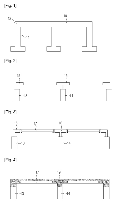
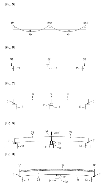
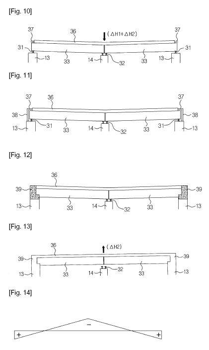
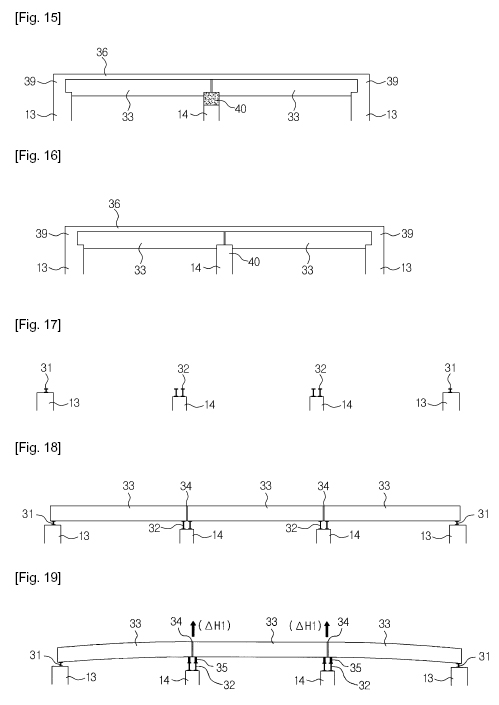
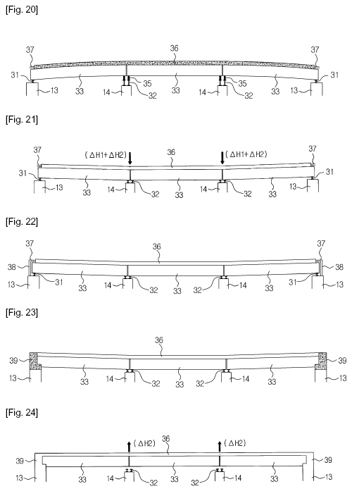
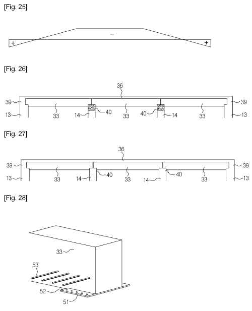
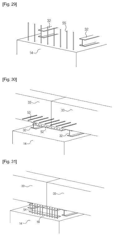
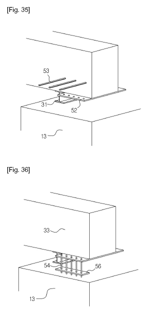
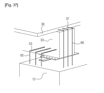
¡¼DESCRIPTION¡½ ¡¼Invention Title¡½ CONTINUOUS COMPOSITE RAHMEN BRIDGE SYSTEM USING PRECAST GIRDER AND CONSTRUCTION METHOD THEREOF ¡¼Technical Field¡½ The present invention relates to a continuous composite Rahmen bridge system using precast girders and a construction method thereof, and more particularly, to a system for construction of a bridge having structural safety and broad applicability and a construction method thereof. ¡¼Background Art¡½ A conventional reinforced concrete Rahmen bridge, as illustrated in FIG. 1, consists only of a slab 10 and columns 11, and thus, the cross section of joints 12 between the slab 10 and the columns 11 needs to be increased to provide adequate support. However, increasing the cross section may disadvantageously increase dead load and also, decrease an overhead clearance of the bridge. For this reason, the slab type Rahmen bridge has been applied only to bridges having a substantially short span, and general bridges using precast girders have been applied to bridges requiring a long span. One example of a solution enabling the above-described Rahmen bridge to be applied to a long-span bridge is Korean Registered Patent Publication NO. 10-0543969 entitled ¡°Composite Rahmen bridge in which pre-stressed composite girder is installed to the center of slab and is connected to steel rod embedded in top of column and construction method thereof¡± (hereinafter, referred to as ¡°cited invention¡±). FIGS. 2 to 5 illustrate a construction method of a two-span continuous Rahmen bridge of the cited invention. Referring to the drawings, in the construction method of the cited invention, after an outer steel rod 15 and an inner steel rod 16 are embedded respectively in upper ends of an abutment 13 and a bridge pier 14 (see FIG. 2), a prefabricated pre-stressed composite girder (i.e. a precast girder) 17 is connected to the outer steel rod 15 and the inner steel rod 16 (see FIG. 3), and thereafter, a slab-forming concrete 19 is applied to cover the steel rods 15 and 16 and the precast girder 17, completing the bridge (see FIG. 4). However, in the above-described cited invention, the precast girder encounters positive moment Mp and negative moments Mn1 and Mn2 caused by dead and live loads as illustrated in FIG. 5. Although the positive moment Mp may be cancelled out by pre-stressing the prefabricated precast girder, there is no method of canceling out the negative moments Mn1 and Mn2 generated at inner and outer positions. The negative moments Mn1 and Mn2 may cause cracks in the slab-forming concrete at the inner and outer positions, having a serious effect on the safety of the bridge, thus necessitating periodic maintenance thereof. ¡¼Disclosure¡½ ¡¼Technical Problem¡½ Accordingly, the present invention proposes a new construction method to overcome the problems of the above-described general Rahmen bridge and the cited invention, and an object of the present invention is to provide a structurally sound continuous composite Rahmen bridge system using precast girders in which compressive force is introduced to cancel out negative moments generated at inner and outer positions, and a construction method thereof. ¡¼Technical Solution¡½ In accordance with one aspect of the present invention, the above and other objects can be accomplished by the provision of a continuous composite Rahmen bridge system using precast girders, wherein negative moment generated at an inner position on a bridge pier of a two or more span continuous Rahmen bridge is canceled out by compressive force introduced by primarily raising and lowering precast girders at the inner position and negative moment generated at an outer position on an abutment is canceled out by compressive force introduced by secondarily raising the precast girders at the inner position. In accordance with another aspect of the present invention, there is provided a continuous composite Rahmen bridge system using precast girders, including an abutment and a bridge pier of a two or more span continuous Rahmen bridge, an outer provisional member provided at an upper end of the abutment and an inner provisional member provided at an upper end of the bridge pier, precast girders installed on the outer provisional member and the inner provisional member so as to be brought into contact with each other above the inner provisional member, compressive force being previously introduced into the precast girders, a supporting member provided above the inner provisional member and serving to maintain a height of the precast girders at the raised level, slab-forming concrete applied over the precast girders, abutment connection concrete to integrate the abutment, precast girders and slab-forming concrete with one another, and bridge pier connection concrete to integrate the bridge pier and precast girders with each other. The slab-forming concrete may be applied after the precast girders are primarily raised from the inner support provisional member by use of the supporting member, the abutment connection concrete is applied after the precast girders may be lowered, and the bridge pier connection concrete may be applied after the precast girders are secondarily raised. A change in height of secondary raising may be smaller than a change in height of primary raising. The precast girders may be unit precast girders independently fabricated on a per span basis and are selected from among pre-stressed concrete girders, preflex girders and steel-box girders. In accordance with a further aspect of the present invention, there is provided a construction method of a continuous composite Rahmen bridge system using precast girders, including installing an outer provisional member and an inner provisional member on an abutment and a bridge pier respectively, placing unit precast girders, which are independently fabricated on a per span basis, on the outer provisional member and the inner provisional member, connecting the placed precast girders to each other above the inner provisional member, primarily raising the connected precast girders from the inner provisional member, applying and curing slab-forming concrete, lowering the primarily raised precast girders, applying and curing abutment connection concrete to integrate the abutment, precast girders and slab-forming concrete with one another, secondarily raising the lowered precast girders, and applying and curing bridge pier connection concrete to integrate the bridge pier and the precast girders with each other. Connection of the precast girders and the bridge pier at the inner position may include placing the precast girders, provided at a side surface thereof with girder reinforcing rods and at a lower end thereof with a connection plate, on the provisional member above the bridge pier, fitting connection reinforcing rods through the connection plate and an anti-drawing plate, connecting bridge pier reinforcing rods protruding from the bridge pier to the girder reinforcing rods, and applying the connection concrete surrounding all the elements so as to integrate the bridge pier and the precast girders with each other. Connection of the precast girders and the abutment at the outer position may include placing the precast girders, provided at the side surface thereof with the girder reinforcing rods and at the lower end thereof with the connection plate, on the provisional member above the abutment, fitting the connection reinforcing rods through the connection plate and the anti-drawing plate, connecting abutment reinforcing rods protruding from the abutment to the girder reinforcing rods, connecting abutment end reinforcing rods protruding from an end of the abutment to slab-forming concrete reinforcing rods protruding from the slab-forming concrete, and applying the connection concrete surrounding all the elements so as to integrate the abutment and the precast girders with each other. ¡¼Advantageous Effects¡½ A continuous composite Rahmen bridge system using precast girders and a construction method thereof according to the present invention can introduce compressive force to slab-forming concrete on the top of an abutment, thereby enabling construction of a structurally sound bridge, which has been impossible by any conventional methods. For example, negative moment generated at an inner position on a bridge pier is canceled out by compressive force introduced by primarily raising and lowering precast girders at the inner position and negative moment generated at an outer position on an abutment is canceled by compressive force introduced by secondarily raising the precast girders at the inner position to or slightly above a horizontal level, whereby construction of a structurally sound bridge can be accomplished. Further, integration of lower structures including the abutment and the bridge pier and upper structures including the precast girders enables construction of a more statically indeterminate structure. This can increase moment distribution effects, reducing vibration due to live load and increasing the ability of the bridge to withstand dynamic load such as in the event of an earthquake. Moreover, as moment generated by external force is distributed to the integrated bridge pier, the precast girders may be less affected by external force, having a reduced height and extended span length and consequently, enabling economical bridge construction. In addition, since the Rahmen bridge has no bearing, the Rahmen bridge may have an increased water-supply cross section and economical efficiency owing reduction in the amount of earthwork of peripheral connection railways. ¡¼Description of Drawings¡½ The above and other objects, features and other advantages of the present invention will be more clearly understood from the following detailed description taken in conjunction with the accompanying drawings, in which: FIG. 1 is a view schematically illustrating a conventional reinforced concrete Rahmen bridge; FIGS. 2 to 5 are views illustrating a construction method of a conventional two-span continuous Rahmen bridge; FIGS. 6 to 16 are views illustrating a two-span continuous composite Rahmen bridge system using precast girders and a construction method thereof according to one embodiment of the present invention; FIGS. 17 to 27 are views illustrating a three-span continuous composite Rahmen bridge system using precast girders and a construction method thereof according to another embodiment of the present invention; FIGS. 28 to 32 are views illustrating a process of connecting a precast girder to a bridge pier at an inner position in the construction method of the continuous composite Rahmen bridge system; and FIGS. 33 to 37 are views illustrating a process of connecting a precast girder to an abutment at an outer position in the construction method of the continuous composite Rahmen bridge system. ¡¼Best Mode¡½ Reference will now be made in detail to the embodiments of the present invention, examples of which are illustrated in the accompanying drawings, wherein like reference numerals refer to like elements throughout. FIGS. 6 to 16 and FIGS. 17 to 27 are views respectively illustrating two-span and three-span continuous composite Rahmen bridge systems using precast girders and construction methods thereof according to the embodiments of the present invention. Referring to the drawings, to construct the two-span continuous composite Rahmen bridge system using precast girders according to the embodiment, first, as illustrated in FIG. 6, in a state in which two abutments 13 and a bridge pier 14 are constructed, outer provisional members 31 and an inner provisional member 32 are placed on upper ends of the abutments 13 and the bridge pier 14 respectively. Here, these provisional members 31 and 32 have predetermined heights in consideration of nominal height adjustments which must be made in order to introduce compressive force into slab-forming concrete. Then, two precast girders 33, which have been pre-stressed through introduction of compressive force, are placed on the upper ends of the abutments 13 and the bridge pier 14 such that both facing ends of the two precast girders 33 are brought into contact with each other above the inner provisional member 33, and then are connected to each other (see FIG. 7). Next, after the connected precast girders 33 are raised at an inner position corresponding to the bridge pier 14 by ¥ÄH1, a supporting member 35 serving to maintain the height of the precast girders 33 at the raised level is installed on the inner provisional member 32 as illustrated in FIG. 8. Then, slab-forming concrete 36 is applied, as illustrated in FIG. 9. In this case, the slab-forming concrete 36 is applied such that reinforcing rods 37 provided at both ends of the slab-forming concrete 36 above the two abutments 13 are partially exposed to the outside. The exposed portions of the reinforcing rods 37 are used to integrate the abutments 13, the precast girders 33 and the slab-forming concrete 36 with one another in a subsequent process. After curing the applied slab-forming concrete 36, in order to introduce compressive force, corresponding to the negative moment Mn2 generated at the inner position as illustrated in FIG. 5, into the slab-forming concrete 36, the primarily raised precast girders 33 are lowered (see FIG. 10). In this case, the precast girders 33 are lowered by ¥ÄH1+¥ÄH2 (¥ÄH1 is a change in height of primary raising, and ¥ÄH2 is a change in height of secondary raising required to introduce compressive force corresponding to the negative moment Mn1). For reference, ¥ÄH2 is 15~30% of ¥ÄH1 because, in the case of the continuous Rahmen bridge system under the influence of live load, the negative moment generated at the outer position on the abutment is smaller than the negative moment generated at the inner position on the bridge pier and also, because the secondary raising occurs in a state in which the abutment is integrated with the precast girders and thus, the degree of static indeterminacy increases by two, allowing greater compressive force to be introduced into the slab-forming concrete on the abutment even when ¥ÄH2, the change in height of secondary raising is small. Next, after connecting the reinforcing rods 37 protruding from both ends of the slab-forming concrete 36 above the abutments 13 and reinforcing rods 38 protruding upward from the upper ends of the abutments 13 to each other as illustrated in FIG. 11, abutment-connection concrete 39 is applied to integrate the abutments 13, the precast girders 33, and the slab-forming concrete 36 with one another as illustrated in FIG. 12. After curing the applied abutment-connection concrete 39, the precast girders 33, which have been lowered by ¥ÄH1+¥ÄH2, are secondarily raised by ¥ÄH2 at the inner position on the bridge pier 14 by use of a conventional hydraulic jack (not shown) (see FIG. 13). Thereby, moment as illustrated in FIG. 14 is generated, allowing compressive force, corresponding to the negative moment Mn1 of FIG. 5 generated in the two-span continuous Rahmen bridge, to be introduced into the upper ends of the abutments 13. Next, if bridge pier connection concrete 40 is applied to integrate the precast girders 33 and the bridge pier 14 with each other as illustrated in FIG. 15, the two-span continuous composite Rahmen bridge system using the precast girders as illustrated in FIG. 16 is completed by the above-described construction method according to the present embodiment. FIGS. 17 to 27 are views illustrating a construction method of a three-span continuous composite Rahmen bridge system using precast girders according to another embodiment of the present invention. A description related to sequential steps of the construction method is identical to that of the above-described construction method of the two-span continuous composite Rahmen bridge system. Similar to a configuration difference between a general two-span bridge and a general three-span bridge, the construction method of the three-span continuous composite Rahmen bridge system according to the present embodiment differs only in that one bridge pier is added and thus, elements installed on the added bridge pier, such as an inner provisional member, a supporting member, and bridge pier reinforcing rods, are added and in that the two bridge piers are simultaneously subjected to primary raising and lowering and the secondary raising. The continuous composite Rahmen bridge system using precast girders according to the embodiments of the present invention will be summarized as follows. In the two or more span continuous composite Rahmen bridge system using precast girders according to the embodiments of the present invention, the negative moment generated at the inner position on the bridge pier can be canceled out by compressive force introduced into the slab-forming concrete on the abutment by primarily raising and lowering the precast girders at the inner position, and the negative moment generated at the outer position on the abutment is canceled out by compressive force introduced into the slab-forming concrete on the abutment by secondarily raising the precast girders at the inner position to or slightly above a horizontal level, whereby the structurally sound continuous composite Rahmen bridge system using precast girders can be accomplished. In the construction method of the continuous composite Rahmen bridge system using precast girders according to the present invention, the used precast girders may be selected from among pre-stressed concrete girders, preflex composite girders, steel-box girders, and the like. Here, differently from precast girders, steel-box girders do not need pre-stressing in the positive moment range. Hereinafter, in the construction method of the continuous composite Rahmen bridge system using precast girders, a process of connecting the precast girder to the abutment at the outer position and a process of connecting the precast girder to the bridge pier at the inner position will be described. FIGS. 28 to 32 are views illustrating a process of connecting the precast girder to the bridge pier at the inner position in the construction method of the continuous composite Rahmen bridge system. FIG. 28 is a perspective view illustrating a connection plate 52 having rod fitting holes 51 perforated at a predetermined interval, which is arranged at a lower end of the precast girder 33 to be connected to the bridge pier 14, and girder reinforcing rods 53 protruding from the precast girder 33. The connection plate 52 serves to connect the precast girder 33 to connection reinforcing rods 54 which are required to connect the bridge pier 14 and the precast girder 33 to each other as described in FIG. 31. The girder reinforcing rods 53, as illustrated in FIG. 29, are connected to bridge-pier reinforcing rods 55 which are embedded in the bridge pier 14 during construction of the bridge pier 14 so as to protrude upward from an upper surface of the bridge pier 14. FIG. 29 illustrates the inner provisional member 32, which is installed on the bridge pier 14 prior to placing the prefabricated precast girder 33 on the bridge pier 14, and the bridge-pier reinforcing rods 55 which are embedded during construction of the bridge pier 14 so as to protrude upward from the upper surface of the bridge pier 14. When the prefabricated precast girders 33 illustrated in FIG. 28 are placed above the bridge pier 14 illustrated in FIG. 29 so as to be brought into contact with each other above the inner provisional member 32, the precast girders 33 and the bridge pier 14 are arranged as illustrated in FIG. 30. Here, for more clear understanding of the drawing, the bridge-pier reinforcing rods 55, which are embedded into the bridge pier 14 so as to protrude upward from the upper surface of the bridge pier 14 as illustrated in FIG. 29, are not illustrated. After placing the precast girders 33 as illustrated in FIG. 30, the connection reinforcing rods 54, which are required to connect the bridge pier 14 and the precast girders 33 to each other, are fitted through the rod fitting holes 51 of the connection plate 52, and an anti-drawing plate 56 is installed to prevent drawing of the precast girders 33 due to downward load and to enable connection of all the connection reinforcing rods 54 (see FIG. 31). Simultaneously, as illustrated in FIG. 32, to connect the upper precast girders 33 and the lower bridge pier 14 to each other so as to construct a completely integrated structure, the bridge-pier reinforcing rods 55, which are embedded in the bridge pier 14 during construction of the bridge pier 14 so as to protrude upward from the upper surface of the bridge pier 14, and the girder reinforcing rods 53 protruding from the precast girders 33 are connected to each other. In FIG. 32, for more clear understanding of the drawing, the connection reinforcing rods 54 and the anti-drawing plate 56 illustrated in FIG. 31, and the slab-forming concrete applied over the precast girders 33 are not illustrated. Next, as illustrated in FIGS. 15 and 26, the bridge pier connection concrete 40, which surrounds all the elements described in the process of FIGS. 28 to 32, is applied to completely integrate the upper precast girders 33 and the lower bridge pier 14 with each other. The above-described process of connecting the inner bridge pier 14 and the precast girders 33 to each other may be equally applied to a process of connecting the precast girders 33 and the outer abutment 13 to each other as will be described hereinafter. FIGS. 33 to 37 are views illustrating a process of connecting the precast girder to the abutment at the outer position in the construction method of the continuous composite Rahmen bridge system. FIG. 33 is a perspective view illustrating the connection plate 52 having the rod fitting holes 51 perforated at a predetermined interval, which is arranged at the lower end of the precast girder 33 to be connected to the abutment 13, and the girder reinforcing rods 53 protruding from the precast girder 33. The connection plate 52 serves to connect the precast girder 33 to the connection reinforcing rods 54 which are required to connect the abutment 13 and the precast girder 33 to each other as described in FIG. 36. The girder reinforcing rods 53 are connected to abutment reinforcing rods 65 which are embedded in the abutment 13 during construction of the abutment 13 so as to protrude upward from an upper surface of the abutment 13 as illustrated in FIG. 34. FIG. 34 is a perspective view illustrating the outer provisional member 31, which is installed on the abutment 13 prior to placing the prefabricated precast girder 33 on the abutment 13, and the abutment reinforcing rods 65 which are embedded during construction of the abutment 13 so as to protrude upward from the upper surface of the abutment 13. Here, in the case of the abutment 13, abutment end connection reinforcing rods 66 are additionally embedded in the abutment 13 to protrude upward from the abutment 13, and are connected to the reinforcing rods 37 protruding from the slab-forming concrete 36 toward a distal end of the precast girder 33. When the prefabricated precast girder 33 illustrated in FIG. 33 is placed above the abutment 13 illustrated in FIG. 34, the precast girder 33 and the abutment 13 are arranged as illustrated in FIG. 35. Here, for more clear understanding of the drawing, the abutment reinforcing rods 65, which are embedded in the abutment 13 upon construction of the abutment 13 so as to protrude upward from the upper surface of the abutment 13 as illustrated in FIG. 34, are not illustrated. After placing the precast girder 33 as illustrated in FIG. 35, the connection reinforcing rods 54, which are required to connect the abutment 13 and the precast girder 33 to each other, are fitted through the rod fitting holes 51 of the connection plate 52, and the anti-drawing plate 56 is installed to prevent drawing of the precast girder 33 due to downward load and to enable connection of all the connection reinforcing rods 54 (see FIG. 36). Simultaneously, as illustrated in FIG. 37, to connect the upper precast girder 33 and the lower abutment 13 to each other so as to construct a completely integrated structure, the abutment reinforcing rods 65, which are embedded during construction of the abutment 13 so as to protrude upward from the upper surface of the abutment 13, and the girder reinforcing rods 53 protruding from the precast girder 33 are connected to each other. The reinforcing rods 37, which are exposed out of the cured slab-forming concrete 36, are connected to the abutment end connection reinforcing rods 66. In FIG. 37, for more clear understanding of the drawing, the connection reinforcing rods 54 and the anti-drawing plate 56 illustrated in FIG. 36 are not illustrated. Next, as illustrated in FIGS. 12 and 23, the abutment connection concrete 39, which surrounds all the elements described in the process of FIGS. 33 to 37, is applied to completely integrate the upper precast girder 33 and the lower abutment 13 with each other. ¡¼Mode for Invention¡½ Various embodiments have been described in the best mode for carrying out the invention. ¡¼Industrial Applicability¡½ The present invention is applicable to a continuous composite Rahmen bridge system using precast girders to achieve structural safety and broad applicability and a construction method thereof. Although the preferred embodiments of the present invention have been disclosed for illustrative purposes, those skilled in the art will appreciate that various modifications, additions and substitutions are possible, without departing from the scope and spirit of the invention as disclosed in the accompanying claims. ¡¼CLAIMS¡½ ¡¼Claim 1¡½ A continuous composite Rahmen bridge system using precast girders, wherein negative moment generated at an inner position on a bridge pier of a two or more span continuous Rahmen bridge is canceled out by compressive force introduced by primarily raising and lowering precast girders at the inner position and negative moment generated at an outer position on an abutment is canceled out by compressive force introduced by secondarily raising the precast girders at the inner position. ¡¼Claim 2¡½ A continuous composite Rahmen bridge system using precast girders, comprising: an abutment and a bridge pier of a two or more span continuous Rahmen bridge; an outer provisional member provided at an upper end of the abutment and an inner provisional member provided at an upper end of the bridge pier; precast girders installed on the outer provisional member and the inner provisional member so as to be brought into contact with each other above the inner provisional member, compressive force being previously introduced into the precast girders; a supporting member provided above the inner provisional member and serving to maintain a height of the precast girders at the raised level; slab-forming concrete applied over the precast girders; abutment connection concrete to integrate the abutment, precast girders and slab-forming concrete with one another; and bridge pier connection concrete to integrate the bridge pier and precast girders with each other. ¡¼Claim 3¡½ The continuous composite Rahmen bridge system according to claim 2, wherein: the slab-forming concrete is applied after the precast girders are primarily raised from the inner provisional member by use of the supporting member; the abutment connection concrete is applied after the precast girders are lowered; and the bridge pier connection concrete is applied after the precast girders are secondarily raised. ¡¼Claim 4¡½ The continuous composite Rahmen bridge system according to claim 3, wherein a change in height of secondary raising is smaller than a change in height of primary raising. ¡¼Claim 5¡½ The continuous composite Rahmen bridge system according to any one of claims 2 to 4, wherein the precast girders are unit precast girders independently fabricated on a per span basis and are selected from among pre-stressed concrete girders, preflex girders and steel-box girders. ¡¼Claim 6¡½ A construction method of a continuous composite Rahmen bridge system using precast girders, comprising: installing an outer provisional member and an inner provisional member on an abutment and a bridge pier respectively; placing unit precast girders, which are independently fabricated on a per span basis, on the outer provisional member and the inner provisional member; connecting the placed precast girders to each other above the inner provisional member; primarily raising the connected precast girders from the inner provisional member; applying and curing slab-forming concrete; lowering the primarily raised precast girders; applying and curing abutment connection concrete to integrate the abutment, precast girders and slab-forming concrete with one another; secondarily raising the lowered precast girders; and applying and curing bridge pier connection concrete to integrate the bridge pier and the precast girders with each other. ¡¼Claim 7¡½ The construction method according to claim 6, wherein connection of the precast girders and the bridge pier at the inner position includes: placing the precast girders, provided at a side surface thereof with girder reinforcing rods and at a lower end thereof with a connection plate, on the provisional member above the bridge pier; fitting connection reinforcing rods through the connection plate and an anti-drawing plate; connecting bridge pier reinforcing rods protruding from the bridge pier to the girder reinforcing rods; and applying the connection concrete surrounding all the elements so as to integrate the bridge pier and the precast girders with each other. ¡¼Claim 8¡½ The construction method according to claim 6 or 7, wherein connection of the precast girders and the abutment at the outer position includes: placing the precast girders, provided at the side surface thereof with the girder reinforcing rods and at the lower end thereof with the connection plate, on the provisional member above the abutment; fitting the connection reinforcing rods through the connection plate and the anti-drawing plate; connecting abutment reinforcing rods protruding from the abutment to the girder reinforcing rods; connecting abutment end reinforcing rods protruding from an end of the abutment to slab-forming concrete reinforcing rods protruding from the slab-forming concrete; and applying the connection concrete surrounding all the elements so as to integrate the abutment and the precast girders with each other. ¡¼ABSTRACT¡½ Disclosed are a continuous
composite Rahmen bridge system using precast girders and a construction method
thereof. In the system, negative moment
generated at an inner position on a bridge pier is canceled out by compressive
force introduced by primarily raising and lowering precast girders at the inner
position and negative moment generated at an outer position on the abutment is
canceled out by compressive force introduced by secondarily raising the precast
girders at the inner position to or slightly above a horizontal level, enabling
construction of a structurally sound two or more span continuous bridge. Further, integration of lower structures including
the abutment and the bridge pier and upper structures including the precast
girders enables construction of a statically indeterminate structure. This
increases moment distribution effects, reducing vibration due to live load and
increasing the ability to withstand dynamic load such as in the event of an earthquake.
|
|
||||||||||||||


| |
|
|